EVGA X58 Classified - First Look
by Rajinder Gill on February 27, 2009 5:00 AM EST- Posted in
- Motherboards
Shocking BIOS options
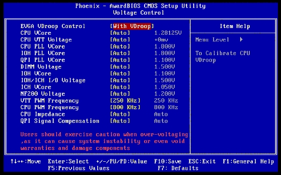
CPU VTT: Stock VTT voltage defaults to 1.17V or so. The scale runs in 10mv steps, allowing you to add or subtract from the base value. VTT voltage drives the integrated memory controller and the QPI link bus. This voltage will need to be increased as you increase memory frequency and increase BCLK (QPI frequency). Remember to keep this voltage within 0.5V of VDIMM to prevent damage to the integrated memory controller.
CPU PLL VCore: 1.8V base; we found no benefits to increasing this voltage for overclocking. Clean power to PLL circuits is essential for ensuring that external influences over the accuracy of clock signals is minimized. It seems EVGA have done a good job with regards to all PLL voltage rails on the Classified. In terms of overclocking headroom and PLL's, clean power always trumps more voltage, thus there's no need to tinker with these voltages to any great extent on this board, apart from perhaps QPI PLL. Even then, you'll probaby find the level of voltage required for maximum BCLK potential is far below what some other boards need to get the same clocks...
IOH PLL VCore: Input/Output Hub Phase Locked Loop voltage. The default voltage is 1.8V. For the most part this voltage can be left at stock unless chasing maximum QPI frequencies for benchmarking. For 24/7 use we recommend you stick with a maximum of 1.89V. Processors/IOHs needing more than 1.89V to remain stable are best run at a lower BCLK and higher CPU multiplier to bring them back into their comfort zone.
QPI PLL VCore: Quick Path Interconnect Phase Locked Loop voltage. For 24/7 overclocking this voltage can be left at stock in most instances. Again, if you need to use more it's probably wise to pull back a little on QPI frequency to a speed that requires no more than 1.2V. For benchmarking, we used 1.45V to reach 239 BCLK for a CPU-Z shot.
IOH VCore: Input/Output Hub voltage uses a 1.10V base. Stock values usually suffice for 24/7 overclocking even when using multiple graphics cards; we had no problems in reaching a stable 200 BCLK X20 for 4GHz CPU speed. For more extreme QPI frequencies this voltage will need to be increased. For 3D benchmarking past 220 BCLK we used 1.45V. We needed 1.50V to reach 239 BCLK. Values over 1.50V failed to POST or locked up in the OS; use only as much voltage as you need.
IOH/ICH I/O Voltage: IOH to Intel Southbridge termination voltage. We left this voltage at stock and did not see any overclocking improvements from increasing it on this board. Base value is 1.50V.
ICH VCore: 1.05V base voltage; again this voltage can be left at default.
NF200 Voltage: 1.2V stock. We left this voltage at stock for all overclocking.
VTT PWM Frequency: Changes the switching frequency of the VTT voltage line. Higher switching frequencies can help facilitate lower output ripple, and reduce overshoot while providing a higher frequency power bandwidth to the CPU. Setting a higher frequency with this BIOS option may improve overclocking headroom somewhat depending on the current drawn. For overclocking past 220 BCLK we generally used 490KHz; for speeds below this a 250KHz switching frequency worked fine for us and also reduces the heat output from the PWM FETs.
CPU PWM Frequency: CPU PWM (VCore supply) switching frequency. Stock is 800KHz, which is more than sufficient for 99% of overclocking. For subzero benchmarking you may wish to increase the switching frequency to see if it helps stability during heavy 8-thread CPU loads. The side effect in doing so is increased heat from the power FETs, although the temperature increase is quite small due to the use of a 10-phase power delivery circuit, especially as the FETs are indirectly cooled via the CPU power plane when the processor temperature is well into the negative region.
CPU Impedance: Sets the level of signal compensation for the QPI bus to the CPU. Higher QPI frequencies often demand a higher signal current, which means that compensation levels have to be changed in order to counter any signal line reflections caused by PCB traces and input impedance mismatches. The options available for this function are AUTO and Less. On the Classified, we found that QPI frequencies approaching 4GHz can benefit from a reduction in setting Less, even more so if the CPU frequency is well above 4.5GHz. Leave at AUTO for most 24/7 overclocking at BCLKs under 200MHz. For subzero cooling at high system speeds, set this value to Less to see if it helps with overclocking headroom.
QPI Compensation: Sets the level of signal compensation for the QPI bus to the IOH. There are three options for this function, those being AUTO, Less, and More. We found that IOH compensation is far more sensitive to changes in compensation values than the CPU. A setting of Less for high BCLKs and QPI frequencies almost always brings about additional system stability during benchmarking (at least in our experience). For all other purposes, this value can be left to AUTO.


22 Comments
View All Comments
JarredWalton - Friday, February 27, 2009 - link
I'm not even sure that's the target market. More likely this is just a dog and pony show that EVGA will give to the top overclockers of the world, who will also get free CPUs from Intel, RAM from memory companies, etc. Then they will take all of that and push their system to new levels of performance and overclocking. The net result is that they hope having their top motherboard in the fastest systems in the world will have a trickle down effect and people will assume that their lower end products are also the "best". Honestly, it's mostly marketing if you ask me. EVGA might only make 500-1000 of these boards and call it quits for all we know.Jedi2155 - Friday, February 27, 2009 - link
Amen to that Soul.